WIRELESS COMMUNICATION AND THE NRF24L01+
Wireless Communication has been around for more than 100 years, and has become a necessity in the modern world. In this tutorial we will teach you all about wireless communication, what it is, how to use it, and how the NRF module achieves it.
First off, radio waves are very similar to light waves. Our eyes can only see a very specific piece of the electromagnetic section, the visible light range. Radio waves still function in almost the same was as visible light does. Imagine someone standing on a mountain with a small flashlight. If you were to look at him, you would be the receiver. If you go far enough away you would stop being able to see his light, and would therefore would not be able to see him. Now, let's pretend he got in his car and turned his lights on. Now, you could get even further and still see the light that he is emitting. As you can image, it would be a lot easier to see him at night than during the day when you don’t have the sun interfering with your view.

Radio waves work in this same fashion. The NRF module uses radio waves that have a frequency of 2.4Ghz, the same frequency that Wi-Fi uses. This means that the more Wi-Fi you have around you, the more interference you have.
Range and Ideal Conditions
To get the best range and performance out of your NRF modules, you need to make sure you have “ideal conditions.” So let's talk about what those are and how to maximize your performance.
Line of Sight: The first thing you want when you are trying to receive your best range is a clear line of sight. You want to make sure that nothing is in the way of your transmitter and receiver. While 2.4Ghz signals can go through some small obstacles like walls and trees, it will quickly start to degrade your usable range. Conditions such as weather can also affect this. Radio waves have a very hard time traveling through water, so if it is foggy or raining you will also lose some range.
Radio Interference: Other radio waves that are operating on the same frequency can also impact your range. Systems such as Wi-Fi can create a lot of noise around you making it harder for the NRF to distinguish what it actually wants to read. The best case scenario would be to go out to an open field with very few buildings around.
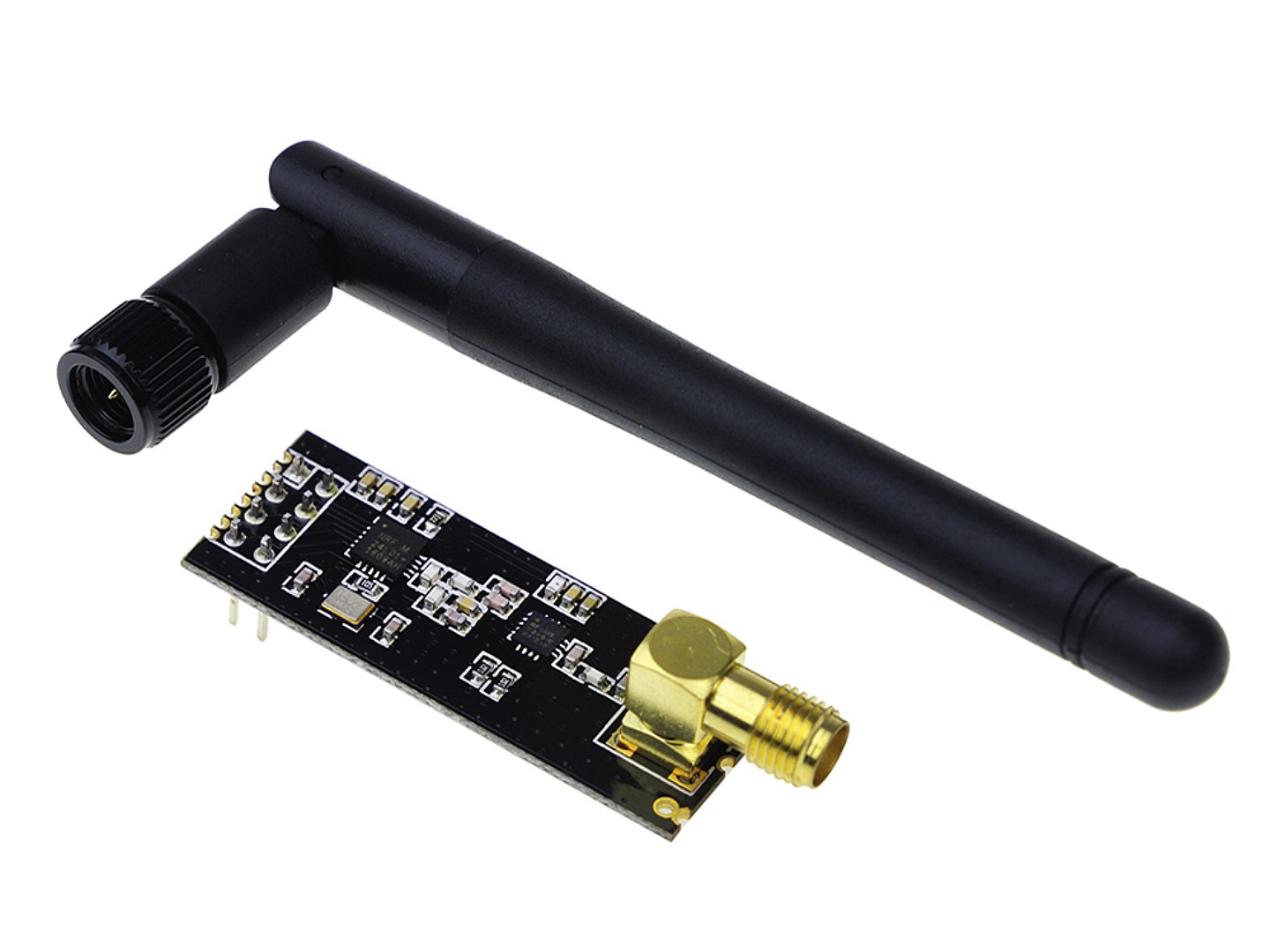
Types of Antenna: For the standard NRF modules the Antenna is a piece of copper that is on the board, so you really can’t do much to change it, but the NRF extended range modules have a detachable antenna that can be changed. We ship out modules with a standard 2.4Ghz “rubber duck” antenna, and these types of antenna are known as omni-directional antennas. This means that they (mostly) radiate the radio waves in all directions. If are controlling a RC car or a drone, then omni-directional will be the best option for you. But if you are communicating with a stationary object, then going and picking yourself up a directional antenna could greatly improve your range.

Power Supply: When these modules are in Maximum Power Mode, they can suck up quite a bit of power. It is important that you have a very good 3.3 Volt power supply with your NRF modules. Radio modules are also very sensitive to voltage ripple. The best way to solve the voltage ripple problem is to solder on a capacitor to the power and ground pins of the NRF. The Pilot RC comes with a dedicated 3.3V regulator and a 100uF capacitor for smoothing out the voltage signals. But this should be taken into consideration when plugging the NFR into other devices.
How does the NRF work?
The NRF24L01+ is both a transmitter and receiver, which means is can switch between either role depending on what you need. For this example we will be talking about how to do a simple one way transmission. You can download the example code and modify it to your heart's content.
The first thing to do is to set up data to be sent. We do this with something called structs, which can hold multiple variables. In this example we are sending the raw data from the joysticks. So, we have 4 axis and 2 push button variables to send. The NRF can send up to 32 bytes per message. The list for how much each type of variable takes up is below.
Double -- 4 Bytes
Int -- 2 Bytes
Boolean -- 1 Byte
For this example each axis will be an Int and the push buttons will be Boolean’s. So, the total message only takes up 10 Bytes of information.
Example Code for Wireless COMMUNICATION
TRANSMITTER code
For the tutorial we will use the One Way Communication available in the Downloads page.
The first thing that we need to do is include all libraries that we will use with this code. The SPI library comes with the Arduino IDE, but you will need to download the RF24 library using the library manager.
Then, we assign the CE and CSN pins for the NRF. These are 7 and 8 on the Pilot RC board.
<#include <SPI.h>
#include "RF24.h"

#define  CE_PIN  7
#define  CSN_PIN 8

RF24 radio(CE_PIN, CSN_PIN);
The next thing to do is is open “pipes”. You can learn more about them in the Nordic datasheet for the NRF24L01+, but they are pretty much “wireless lanes” for communication. These needs to be the same for both the master and the slave.
byte addresses[][6] = {"1Node", "2Node"};
Now, we set up the data that we want to send in each transmission. For this task, we will use data structs. Structs can hold multiple variables, and can access all of them by just calling the name of the struct. In this case, that would be myData. The NRF can only send 32 bytes in each transmission, so make sure not to make the struct more than that.
struct dataStruct {       //this is the NRF data. Max of 32 bytes
  int Xposition;          //int     = 2 bytes
  int Yposition;          //double  = 4 bytes
  bool switchOn;          //boolean = 1 byte

  int X2position;
  int Y2position;
  bool switch2On;
} myData;
Now for the setup loop. To start, initialize the radio and set its channel. The function, radio.setChannel() sets what frequency the master and slave will talk to each other. This needs to be the same on both devices for them to correctly talk to each other. The following equitation for frequency and channel is: 2.4Ghz + 0.108Ghz = 2.508Ghz
We use 2.508Ghz because it is above most Wi-Fi channels so there will be little interference.
radio.begin();
radio.setChannel(108);
Now, set the data rate. Again this needs to be the same for both the master and the slave. This examples uses 250KBPS, but the NRF can go as fast as 2MBPS. 250KBPS also gives us better range.
We also need to set the power level of the NRF. For this example we set the power level to minimum because the NRF can actually draw quite a bit of power. Trying to power the NRF through USB power at maximum power level will likely not work. If you would like to transmit at full power, make sure a battery is connected to the battery terminals of the Pilot RC so that the NRF will have dedicated power from the 3.3V regulator.
radio.setDataRate(RF24_250KBPS);
radio.setPALevel(RF24_PA_MIN);
The last setup step is to open a reading and writing pipe for the NRF module. Then we need to tell the transmitting NRF to stop listening and go into transmit mode.
radio.openWritingPipe(addresses[0]);
radio.openReadingPipe(1, addresses[1]);
radio.stopListening();
Now that the setup is over, we only need one line in the loop to transmit data. We want to write the myData struct that has all of the data we would like to send.
radio.write(&myData, sizeof(myData), 1);
This is all the code you need for the transmitter for the One Way Communication example.
RECEIVER Code
The code to receive the message is very much the same. The only difference in the setup is that the reading and writing pipes need to be flipped on the receiving NRF. If they are both writing and reading on the same pipe, they will never hear each other. Then we just tell the NRF to start listening for a transmission.
radio.openWritingPipe(addresses[1]);
radio.openReadingPipe(1, addresses[0]);
radio.startListening();
For the loop, we use an IF statement to see if there is any data available from the NRF. If there is, then we read that data and print it out! That is all the code you need for the receiving module.
if (radio.available()) {
    radio.read( &myData, sizeof(myData) );
    Serial.print(myData.Xposition);  Serial.print("\t");
    Serial.print(myData.Yposition);  Serial.print("\t");
    Serial.print(myData.switchOn);   Serial.print("\t");
    Serial.print(myData.X2position); Serial.print("\t");
    Serial.print(myData.Y2position); Serial.print("\t");
    Serial.print(myData.switch2On);  Serial.print("\t");
    Serial.println();
  }
Make sure to download the One Way Communication code available in our Downloads page.