Schematic and Board Layout
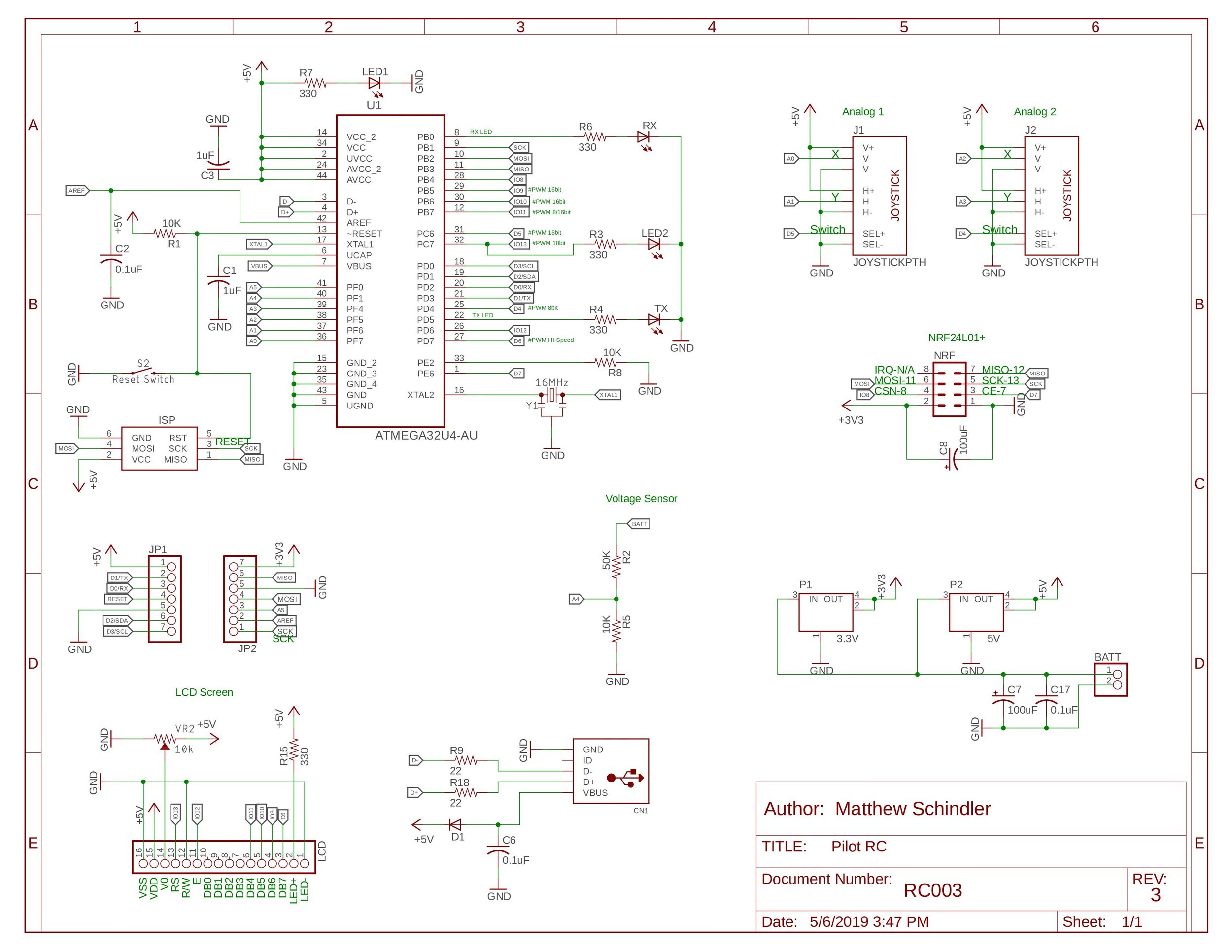
The Schematic for the Board is available here: Schematic
The board layout can be found here: Board Layout
The Eagle Files can be downloaded here: Eagle Files
To learn more technical information: Pilot RC Specs
To code the Pilot RC the Arduino IDE is required. You can download this for free here.
Example Code
Download any of our Free Arduino Code!
This code reads the raw values coming out of the joysticks and push-buttons. This will give you a basic understanding of how the joysticks work and how to interpret their position. Updated: 5/23/2019
This code takes what you learned in the Joystick Basic sketch and interprets that data into usable and accurate data to control your projects. Updated: 5/23/2019
Learn how to use the LCD screen on your Pilot RC and add your own information. Updated: 5/23/2019
Using the on board voltage divider, the Pilot RC can safely read voltages of up to 20 Volts. Use the following code to convert the analog signals to voltage values. Updated: 5/23/2019
Learn how to set up one of your NRF modules as the Master and the other as a Slave. This will send joystick data from one NRF module to the other. The zip file includes both the Transmit and the Receive code. Updated: 6/1/2019
Learn how to set up your NRF modules for two way communication using the acknowledge mode. The zip file includes both the Master and Slave code. Updated: 5/23/2019
This is this self check code that we used to verify all of the systems on the Pilot RC. This code uses all of the board’s features. The board only does a NRF test for 5 seconds before moving on to the next step. Make sure the slave is transmitting before turning on the Pilot RC. Updated: 5/23/2019
3D printing Files

The Pilot RC 3D Printed Case is available for the standard and extended range version. Both 4 mm and 3 mm screw hole diameter sizes are included in the zip file.
This is not the final version of the Pilot RC case, these will be continuously updated.
Last Updated: 5/29/2019