Pilot RC SPECIFICATIONS
The Pilot RC is based on the Arduino Micro. It utilizes the same ATMega32u4 Microcontroller which features a built-in USB. This makes the Pilot RC recognizable as a mouse or keyboard. To learn more about the Arduino Micro click here.
The Pilot RC has 20 digital input/output pins (of which 7 can be used as PWM outputs and 12 as analog inputs), most of which are already pre-connected to features on the board.
Features
Individual 5V and 3.3V Voltage Regulators
Reset Button
ICSP Header
Power, RX, TX, and user programmable LED
4 mm mounting holes
Native USB Communication
LCD Header
NRF Header
Two Joysticks with dual axis control and push-button
Battery voltage sensor and power filtering
User pinout for adding additional items to the board
Built in Potentiometer for LCD contrast
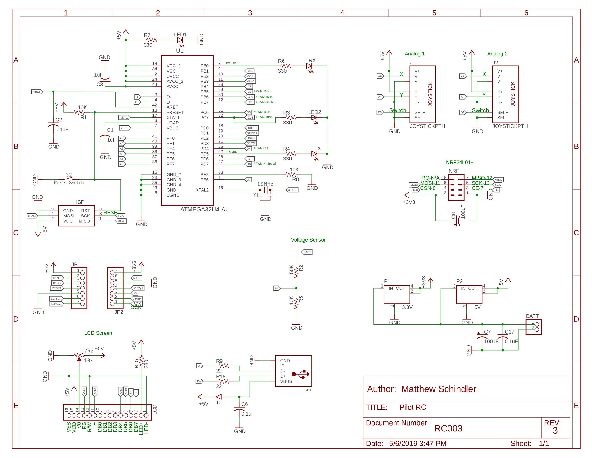
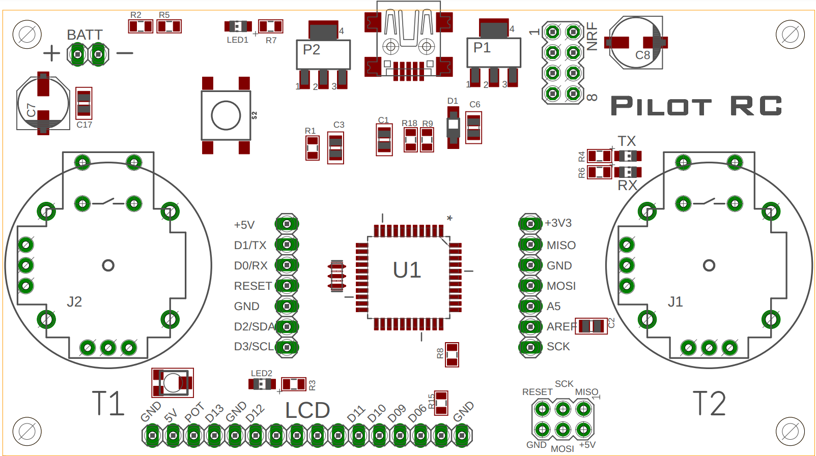
Board Layout and Schematic
To download and view the board layout and schematic, click here.
Pinouts for ACCESSORY Items

Arduino Micro SPECIFICATION
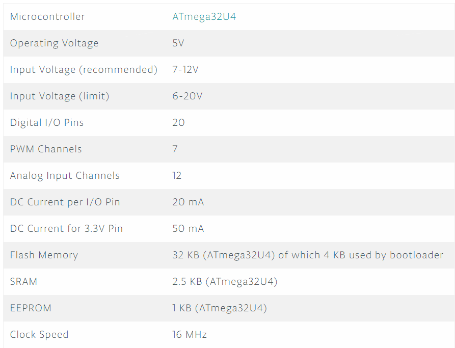
iNPUT AND oUTPUT
Serial: 0 (RX) and 1 (TX). Used to receive (RX) and transmit (TX) TTL serial data using the ATmega32U4 hardware serial capability. Note that on the Pilot RC, the Serial class refers to USB (CDC) communication; for TTL serial on pins 0 and 1, use the Serial1 class.
TWI: 2 (SDA) and 3 (SCL). Support TWI communication using the Wire library.
External Interrupts: 0(RX), 1(TX), 2, 3 and 7. These pins can be configured to trigger an interrupt on a low value, a rising or falling edge, or a change in value. See the attachInterrupt() function for details.
PWM: 3, 5, 6, 9, 10, 11 and 13. Provide 8-bit PWM output with the analogWrite() function.
SPI: on the ICSP header. These pins support SPI communication using the SPI library. Note that the SPI pins are not connected to any of the digital I/O pins as they are on the Uno, they are only available on the ICSP connector and on the nearby pins labelled MISO, MOSI and SCK.
RX_LED/SS This is an additional pin compared to the Leonardo. It is connected to the RX_LED that indicates the activity of transmission during USB communication, but is can also used as slave select pin (SS) in SPI communication.
LED: 13. There is a built-in LED connected to digital pin 13. When the pin is HIGH value, the LED is on, when the pin is LOW, it's off.
Analog Inputs: A0-A5, A6 - A11 (on digital pins 4, 6, 8, 9, 10, and 12). The Pilot RC has a total of 12 analog inputs, pins from A0 to A5 are labelled directly on the pins and the other ones that you can access in code using the constants from A6 trough A11 are shared respectively on digital pins 4, 6, 8, 9, 10, and 12. All of which can also be used as digital I/O. Each analog input provide 10 bits of resolution (i.e. 1024 different values). By default the analog inputs measure from ground to 5 volts, though is it possible to change the upper end of their range using the AREF pin and the analogReference() function.
There are a couple of other pins on the board:
AREF. Reference voltage for the analog inputs. Used with analogReference().
Reset. Bring this line LOW to reset the microcontroller. Typically used to add a reset button to shields which block the one on the board.
COMMUNICATION
The Pilot RC has a number of facilities for communicating with a computer, another board of the Arduino & Genuino family, or other microcontrollers. The 32U4 provides UART TTL (5V) serial communication, which is available on digital pins 0 (RX) and 1 (TX). The ATmega32U4 also allows for serial (CDC) communication over USB and appears as a virtual com port to software on the computer. The chip also acts as a full speed USB 2.0 device, using standard USB COM drivers. On Windows, a .inf file is required. The Arduino Software (IDE) includes a serial monitor which allows simple textual data to be sent to and from the board. The RX and TX LEDs on the board will flash when data is being transmitted via the USB connection to the computer (but not for serial communication on pins 0 and 1).
A SoftwareSerial library allows for serial communication on other Pilot RC's digital pins.
The ATmega32U4 also supports I2C (TWI) and SPI communication. The Arduino Software (IDE) includes a Wire library to simplify use of the I2C bus; see the documentation for details. For SPI communication, use the SPI library.
The Pilot RC appears as a generic keyboard and mouse, and can be programmed to control these input devices using the Keyboard and Mouse classes.
Automatic (Software) Reset and Bootloader Initiation
Rather than requiring a physical press of the reset button before an upload, the Pilot RC board is designed in a way that allows it to be reset by software running on a connected computer. The reset is triggered when the Pilot RC's virtual (CDC) serial / COM port is opened at 1200 baud and then closed. When this happens, the processor will reset, breaking the USB connection to the computer (meaning that the virtual serial / COM port will disappear). After the processor resets, the bootloader starts, remaining active for about 8 seconds. The bootloader can also be initiated by pressing the reset button on the Pilot RC. Note that when the board first powers up, it will jump straight to the user sketch, if present, rather than initiating the bootloader.
Because of the way the Pilot RC handles reset it's best to let the Arduino Software (IDE) try to initiate the reset before uploading, especially if you are in the habit of pressing the reset button before uploading on other boards. If the software can't reset the board, you can always start the bootloader by pressing the reset button on the board...
A huge thanks to the Arduino Community
We at Schindler Electronics would like to thank the Arduino Team for allowing the open source nature of their project to continue and allow others to make projects such as ours. We hope to inspire others to make their own projects just as the Arduino Team inspired us to make ours.
